Tuesday, May 22, 2012

Unit of Traffic - Erlang

Few question can be asked
-> what is the unit of traffic intensity
-> What is Erlang
-> Definition of erlang
-> How erlang is measured
-> What is use of erlang B table
-> Difference between Erlang B and Erlang C table

Here we comes with answers:

Erlang is the unit of telephone traffic intensity. This mane put in honor of danish mathematician.

Definition of Erlang: It is a total traffic volume of one hour (3600 Second).
In other words - one erlang is one channel occupied continuously for one hour.

Erlang calculation can be done via following methods:
1. Erlang B Table
2. Erlang B extended Table
3. Erlang C Table

One important factor GOS (Grade of Service) is consider to read Erlang table. Every operator decides its grade of service.
TRAI (Telecom Regulatory) fixed GOS 2% i.e. 2 calls can be blocked out of 100 calls.

Erlang Table is used to check how many lines required in busiest hour.

Erlang B table is most common used traffic model in telecom sector. This model consider all block calls clear immediately.
Erlang B extended table consider block calls cleared immediately and tried again.
Erlang C table consider all blocked calls queued until traffic channel is assigned.

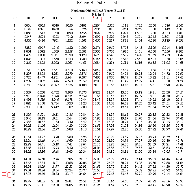
How to read Erlang B Table:
Erlang B table consist GOS in X axis and No. of lines in Y axis. If our system capacity is 26.4 erlang and GOS is 2%, then we see the value of y axis where 26.4 or higher found below 2%. In below picture we can see we will be require 35 lines to satisfy condition.

Friday, January 28, 2011

Is access fail in performance report from BSC is right?

Access fail is a key parameter of CDMA technology. Access fail cannot be measured by performance reports extracted from BSC (Base Station Controller).
We can see access fail in our performance report but it is not actual why?

MS try to access the system and send information on access channel, it is possible that due to poor RF environment BTS (Base Transreceiver System) cannot receive the request and does not acknowledge. After several try of MS access fail has been done and BTS does not aware of this as he did not have any information.
BTS only measures access fail of termination calls and access fail occur after first probe received by itself in case of origination call.
Access fail can be measured by drive test.

Wednesday, January 19, 2011

Communication model of CDMA

Information Stream ----------------->
Speech coding --> Channel coding --> Scrambling --> Spread Spectrum --> Modulation --> RF Transmit

<------------------------------ Information Stream
Speech decoding <-- Channel decoding <-- De-Scrambling <--De-Spread Spectrum <-- De-Modulation <-- RF Receive


 Speech coding

Speech coding is critical to digital transmission. CDMA system uses an efficient method of speech coding and extensive error recovery techniques to overcome the harsh nature of the radio channel.

The objective of speech coding is not only to maintain speech quality but also to reduce the quantity of transmitting data.

Speech coding algorithms (digital compression) are necessary to increase cellular system capacity.

Coding must also ensure reasonable fidelity, that is, a maximum level of quality as perceived by the user.

Coding can be performed in a variety of ways (for example, waveform, time or frequency domain).

Vocoders transmit parameters which control reproduction of voice instead of the explicit, point-by-point waveform description.

Variable Rate Vocoding
  • CDMA uses a superior Variable Rate Vocoder which includes Full rate during speech, Low rates in speech pauses, Increased capacity and More natural sound.
  •  Voice, signaling, and user secondary data may be mixed in CDMA frames. 
  • The output is 20 ms frames at fixed rates:  Full Rate, 1/2 Rate , 1/4 Rate , 1/8 Rate, & Blank. 
  • CRC is added to all the frames for the 13 kb vocoder, but only to the Full and 1/2 rate frames for the 8 kb vocoder.
  • CRC is not added to the lower rate frames in the 8 kb vocoder, but that is ok because they consist mostly of background noise and have a higher processing gain.
  • Current vocoder rates are 8kbps, 13kbps, and 8kbps EVRC (Enhanced Variable Rate Coder)


 Channel coding

Channel coding usually falls into two classes: Block interleave codes and Convolution codes. The objective of channel coding is adding additional supervising bits in the information stream to ensure get correct signal at receive side.

Convolution Encoder & Interleave Encoder

Convolution Encoder: It increases the reliability but reduce the transmitting efficiency, because each code stream adds supervising bit for rectified
Block Interleave Encoder: It does not change the efficiency but have some delays, because the transmitter and receiver must process to writing first and then reading


Scrambling

The paging channel includes many import information such as user’s IMSI, In order to keep the user’s information secret, we use the data scrambling.

Data scrambling function:

Data scrambling is accomplished by modulo-2 addition (XOR),one input is a modulation symbol(19.2ksps) coming out of the block interleaver, another input is a random sequence, which created by decimator on long code generation. That means, Use the 64 times decimator to pick up the first chip of each 64 chips to form a random sequence. So the random sequence rate is 19.2kcps. (1.2288/64)


Spread Spectrum

In CDMA we use Spread code rate: 1.2288Mcps
Following codes are used to make Spread code
  • Forward Link: Walsh code
  • Reverse Link: Long PN code


Direct Sequence Spreading

Output of the randomizer is direct sequence spread by the long code
Each mobile station spreads its reverse traffic channel using the same long PN code but with a different offset, which is determined by a unique 42-bit mask.

The mobile station can use one of two unique long code masks:
  • A public long code mask based on the ESN
  • A private long code mask


Orthogonal Spreading
  • Each symbol output from the Mux is exclusive XORed by the assigned Walsh function
  • Walsh function has fixed chip rate of 1.2288 Mcps
  • Channels are distinguished from each other by Walsh function
  • Bandwidth used greatly exceeds source rate


Modulation

QPSK & OQPSK are the types of modulation
The forward traffic channel is combined with two different PN sequences: “I” and “Q”
Baseband filtering ensures the waveforms are contained within the 1.25 MHz frequency range
The final step is to convert the two baseband signals to radio frequency (RF) in the 800 MHz or 1900 MHz range

Quadri-Phase Shift Key (QPSK) Modulation
  • BASEBAND: The total frequency band occupied by the aggregate of all the information signals used to modulate a carrier
  • FILTER: Electronic circuit devised to modify the frequency distribution of a signal spectrum
  • BASEBAND FILTER: filter (used in quadrature modulation) that limits the input signal to the SyQuest band +-T/2, where T is the transmitted pulse rate.
  • GAIN CONTROL: the gain of the overhead channels (pilot, sync and paging) in the composite I and Q is set. The gain of each forward traffic channel is constantly adjusted by the reverse link power control process.

OQPSK
The reverse traffic channel data after direct sequence spreading is spread in quadrature by adding modulo-2.This stream with the zero-offset I and Q PN short code sequences is used on the forward CDMA channel.

Why a half chip delay in the Q Component?
The data spread by the Q PN short code sequence is delayed by half a PN chip time, 406.901 ns, with respect to the data spread by the I PN short code sequence. This prevents the I and Q to change value simultaneously, thus eliminating diagonal transitions

Monday, January 17, 2011

What is Ec/Io, How it is varied with traffic, Why Ec/Io is always negative

This is a key parameter of CDMA technology measure at mobile station. It shows signal strength of each sector individually. Now question is arises in our mind that signal strength can be measured with RSSI also then why Ec/Io is used because RSSI is sum of signal strength of all sectors received by mobile. To judge signal of each sector Ec/Io parameter is used. That’s why Ec/Io is used to decide handoffs.


Ec/Io is the ratio of pilot power to total power. Total power includes pilot channel power, paging channel power, sync channel power and traffic channel power.
Let’s consider following situation. Here pilot power is 2W and total power is 5.6W. Then Ec/Io is (2/5.6) and it is equal to -4 db (equation is 10* log (2/5.6)).


Traffic channel
2W
Io
Sync channel
1.4W
Paging channel
.2W
Pilot channel
2W


In following situation pilot power is 2W and total power is 9.6 W. Here Ec/Io is (2/9.6) and it is equal to -7 db (equation is 10* log (2/9.6)).


Traffic channel
6W
Io
Sync channel
1.4W
Paging channel
.2W
Pilot channel
2W


Why Ec/Io is always negative?
We can see that Ec/Io is ratio of pilot power to total power (including noise). Now pilot power is always less then total power and ratio value of these will always less than 1. Logarithm of any less than 1 value is always negative. This is the reason why Ec/Io is always negative.

Thursday, January 13, 2011

Power control methods in CDMA

Power control are two types: Forward link power control and reverse link power control
Forward link power control: 
Forward link power control is a loop control and the controlled target is the transmit power of base station. Mobile station plays assistant role.
Fast power control can divide into outer loop power control and closed loop power control. This is a slow process and less efficient.  Both loop work together. The base station continually and slowly decreases power to each mobile station (each user forward traffic channel). MS determine FER and based on that forward traffic channel decrease or increase.

Reverse Link power Control:
Reverse link power control is more accurate. It control mobile transmit power and base station plays a assistant role. It included three types of power control:
1)      Open loop power control
2)      Close loop power control
3)      Outer loop power control
1). Reverse link Open loop power control
Reverse open loop power is mobile station controlling it’s transmit power. Estimating how strong the mobile station should transmit based on a coarse measurement of how much power it is receiving from the base station. Problem in open loop control is that It Assumes same exact path loss in both directions; therefore, cannot account for asymmetrical path loss and Estimates are based on total power received; therefore the power received from other cell sites by mobile station introduces inaccuracies. It uses formula Tx+Rx-Tx_adj = -73dBm.

2). Reverse link close loop power control
It compensates for asymmetries between the forward and reverse paths.
It Consists of power up (0) & power down (1) commands sent to the mobile stations, based upon their signal strength measured at the Base Station and compared to a specified threshold(set point).
Each command requests a 1dB increase or decrease of the mobile station transmit power.
It transmitted 800 times per second, always at full power.
It allows compensating for the effects of fast fading.

3). Reverse link outer loop power control
Base station controller (BSC) determines FER on reverse traffic channel and accordingly set point threshold value is changed.  It will increase reverse capacity and improve voice quality.

Why power control required in CDMA system

CDMA is an interference limited system based on the number of user. Here each user is a noise source on shared cannel. Due to this CDMA system practically has a limit of users who can sustain, this is called soft capacity limit.
Near Far effect is basic feature of CDMA. If we assume that mobile transmit power is same for all user then mobile user near a cell jams a user that is distant from the cell. This problem may be present despite high processing gain. So an effective method to eliminate the near-far effect is necessary.

CDMA system uses power control technique to keep each MS at absolute minimum power level necessary to ensure acceptable service quality. Power control is essential for adjusting BTS and MS transmit power instantly according to communication distance (to overcome near far effect).  Ideally the power received at the base station from each mobile station should be same (Minimum signal to interference).

Wednesday, January 12, 2011

CDMA Frequency Band and calculation

CDMA technology is available is 450 Mhz, 800 Mhz and 1900 Mhz band. Out of these we are using 800 Mhz in current system.
The band is having two electromagnetic channels. One for Base Station to Mobile Station communication (called the FORWARD LINK or the DOWN LINK) and another for Mobile Station to Base Station communication (called the REVERSE LINK or the UP LINK).
In 800 MHz Cellular these two duplex 1.25 MHz bands are 45 MHz apart
In 1900 MHz PCS these two duplex 5 MHz bands are 80 MHz apart
In 450MHz, they are 10MHz apart


CDMA Frequency calculation
450MHz
BS receiver(Uplink): 450.00+0.025(N-1)
BS sender(downlink): 460.00+0.025(N-1)

800MHz
BS receiver(Uplink): 825.00+0.03N
BS sender(downlink):870.00+0.03N

1900MHz
BS receiver(Uplink): 1850.00+0.05N
BS sender(downlink):1930.00+0.05N